Where Coaxial Signal Problems Begin
Incomplete specifications can contribute to coaxial signal problems, alongside assembly defects, installation damage, and component variation. A cable built to an incomplete drawing may not meet the system’s performance requirements.
The gaps repeat across programs. Common ones include:
- A callout that names a cable type and length, but no impedance or frequency range
- Connector part numbers without orientation, gender, or plating detail
- No defined bend radius or routing path, leaving the assembler to improvise
- No strain relief requirement at the connector transition
- No inspection or continuity test criteria, so acceptance becomes subjective
- No revision control, so two suppliers build two different parts from the same part number
Behind most of these is a handoff problem. The RF behavior lives with the design engineer. The purchase order lives with procurement. The physical build lives with the assembler. When the specification does not carry the engineer’s intent all the way to the build instructions, that intent gets lost.
There is also a timing issue. Coaxial assemblies are often specified last, after the board layout is frozen and the enclosure is tooled. By then the routing path is fixed, the connector position is fixed, and the cable has to absorb every compromise. A jumper that must turn twice inside a shallow enclosure is a different part from the same jumper routed straight. Specifying the cable late can leave insufficient space for the required bend radius.
A third source of trouble is substitution. Two cables may share a common designation and still differ in shield coverage, dielectric material, and attenuation per foot. An unapproved substitute may pass continuity testing but exceed the loss budget at the highest operating frequency.
The practical fix is to specify coaxial cable assemblies as engineered components with defined electrical, mechanical, and environmental requirements. The sections that follow break down what belongs in that definition.
Electrical Requirements That Guide Cable Selection
Electrical requirements set the boundaries for every other choice. Once impedance, frequency, and loss budget are fixed, the list of workable cable and connector combinations narrows quickly.
Specify the characteristic impedance required by the system. Select compatible cable and connectors for the intended signal path. Impedance mismatches reflect energy toward the source. Maintain the specified impedance across the cable, connectors, and transitions. An incompatible connector can create an impedance discontinuity. Continuity testing alone does not confirm impedance matching.
Next comes frequency range. The highest operating frequency drives dielectric choice, cable diameter, and connector family. Specify connectors rated for the full operating band. Performance beyond the published rating requires verification. Stating the maximum frequency, not just the nominal one, prevents a connector selection that works today and fails after a product refresh.
Insertion loss deserves a defined budget rather than a general preference. Attenuation generally increases with cable length and operating frequency. Specify acceptable insertion loss across the operating band. Engineering teams that state an acceptable loss figure for the finished assembly give the build team something measurable to hold.
Other electrical parameters worth calling out:
- Voltage standing wave ratio limits across the operating band
- Power handling, particularly for transmit paths and test equipment
- Shielding effectiveness, stated as a target rather than implied
- Velocity of propagation, when timing or phase matching matters
- Phase stability with flexure, for assemblies that move during operation
- Dielectric withstanding voltage, where safety requirements apply
Length is an electrical parameter too, not only a mechanical one. Extra length adds loss, adds cost, and adds material that has to be secured somewhere inside the enclosure. Length tolerance matters just as much. Define length tolerance around the routing path, available clearance, and connector strain limits.
Phase matched sets bring their own requirements. When several assemblies feed a single antenna array or a multichannel receiver, electrical length has to be matched within a stated window. That requirement changes how the assemblies are cut, terminated, and tested, so it belongs in the specification from the start.
Connector Options and Termination Methods
Connector selection balances frequency capability, size, durability, and how the assembly will be handled after installation. The common families each solve a different problem.
- BNC: A bayonet coupling that mates quickly and tolerates frequent connection cycles. Well suited to test points and service access.
- SMA: A threaded interface used widely in compact assemblies and higher frequency paths. Requires controlled torque during mating.
- SMB: A snap on interface for tight spaces and internal jumpers where tool access is limited.
- TNC: A threaded version of the BNC interface, which holds up better under vibration.
- N type: A larger threaded connector used where power handling and weather resistance matter.
Orientation is part of the connector decision. A straight connector extending from a board edge may need clearance the enclosure does not have. Right angle bodies solve that, but they change the mating force direction and the minimum bend point. Specifying orientation on the drawing prevents an assembler from making that call by eye.
Plating affects contact resistance and corrosion behavior. Gold plated center contacts reduce contact resistance and resist tarnish. Nickel and silver plating appear on bodies and outer conductors for wear and conductivity reasons. Plating callouts also matter for mixed metal contact in humid or salt exposed environments.
Termination requirements depend on the selected cable and connector design, and the trade offs between crimped vs. soldered coaxial cable terminations shape that choice. Crimped terminations use a controlled die to compress a ferrule over the braid, producing repeatable results at volume when the tooling and die sets are verified. Follow the connector manufacturer’s termination instructions. Some designs combine a soldered center contact with a crimped ferrule. Validate tooling, process controls, and inspection requirements for the intended application.
Two details often get skipped on drawings. The first is strip length for the center conductor, dielectric, and braid, which directly affects impedance at the transition. The second is the required torque value for threaded connectors, since undertorqued interfaces drift under vibration and overtorqued interfaces deform the mating surface.
Mating cycle count is worth stating as well. An internal jumper installed once has different requirements from a panel connector that field technicians will disconnect regularly. Review the specified mating cycle rating against expected installation, testing, and service use.
Shielding Choices for Electrically Noisy Environments
Shielding does two jobs at once. It keeps external interference out of the signal path, and it keeps the cable from radiating energy into nearby circuits. In electrically noisy equipment, both directions matter.
Shield construction generally falls into a few categories:
- Single braid: A woven metallic layer offering moderate coverage with good flexibility.
- Foil plus braid: A foil layer provides near complete coverage at higher frequencies, while the braid adds mechanical strength and low frequency performance.
- Double braid: Two woven layers for higher shielding effectiveness in demanding installations.
- Semi rigid: A solid outer conductor that delivers very high shielding effectiveness, with the trade off that it holds a formed shape and cannot be routed freely.
- Conformable: A construction that can be shaped like semi rigid cable but reworked more easily during prototyping.
Braid coverage percentage is a useful specification point because it sets a floor. So does shielding effectiveness stated in decibels across the operating band. Without either figure, one supplier’s interpretation of adequately shielded will differ from another’s.
Consider the noise sources in the actual installation. Industrial automation equipment places coaxial runs near motor drives, contactors, and switching power supplies. Factory robotics adds moving cable and changing proximity to noise sources. In these cases the shield termination method matters as much as the shield itself. A braid terminated cleanly to the connector body forms a continuous enclosure around the signal. A pigtail connection to ground creates an inductive path that performs poorly as frequency rises.
Grounding strategy needs a decision, not an assumption. The coaxial outer conductor also carries signal return current. Specify its connections and chassis bonding according to the circuit design. The specification should state which approach applies, because the assembler cannot infer it from the parts list.
Cable construction layers contribute here too. Where the selected cable includes conductive layers, follow the manufacturer’s stripping instructions to preserve the intended electrical connections.
One practical check: if a design already includes filtering, ferrites, or board level shielding to solve an interference problem, the coaxial path deserves the same scrutiny. A well shielded board fed by a marginally shielded jumper is still exposed.
How Routing and Strain Relief Affect Flex Life
Mechanical handling determines how long a coaxial assembly holds its electrical performance. A cable can meet initial electrical requirements but lose performance under repeated movement or vibration.
Minimum bend radius is the starting point. Bending coax tighter than its rating deforms the dielectric and shifts the center conductor away from the center axis. That geometry change alters impedance locally, which raises standing wave ratio and insertion loss. The damage is often invisible from the outside, which makes it hard to diagnose during troubleshooting.
Static and flexing applications call for different constructions. A jumper installed once inside a sealed enclosure can use a construction optimized for loss and size. Select a cable qualified for the required motion, bend radius, and cycle life. Conductor construction alone does not establish flex suitability. Several routing mistakes damage coaxial assemblies quietly, including tight bends at the connector, unsupported cable weight, and service loops crushed during enclosure closeout.
Strain relief protects the transition point where the cable meets the connector. That junction concentrates stress because the cable is flexible and the connector is not. Common approaches include molded boots, heat shrink with adhesive lining, backshells with clamping features, and mechanical clamps placed close to the termination. The right choice depends on the environment and the expected handling.
Practical routing guidance worth capturing on the drawing:
- Define the routing path, not just the endpoints
- Place the first support point near the connector to carry cable weight
- Keep bends away from termination points wherever the layout allows
- Avoid routing alongside sharp enclosure edges or moving mechanisms
- Specify tie down locations so builds stay consistent across units
- Size service loops to the available space, rather than adding slack by default
Vibration adds a separate concern. In transit and vehicle applications, unsupported cable spans can amplify movement under certain vibration conditions. Defined support spacing can reduce cable movement. Validate support locations against the expected vibration profile.
Length tolerance ties back to mechanics too. A cable specified slightly too short gets pulled straight during installation, loading the connector continuously. A cable specified too long gets coiled into whatever space remains, which often means a bend tighter than the rating.
Environmental Demands in Regulated Industries
Environmental requirements often decide which cable constructions remain viable after electrical and mechanical needs are settled. Temperature, moisture, chemical exposure, and vibration each limit material choices.
Temperature range drives dielectric and jacket selection. PVC jackets are cost effective and flexible at moderate temperatures. Fluoropolymer materials such as PTFE and FEP hold up at higher temperatures. They also offer stable electrical properties. The rating needs to reflect the temperature at the cable, not the ambient room temperature. Heat builds inside sealed enclosures.
Moisture and contamination require sealing decisions. Assemblies exposed to washdown, condensation, or weather need connectors with sealing features and jackets that resist water ingress. Marine applications add salt exposure. Salt accelerates corrosion at exposed metallic surfaces. Plating selection and shield termination become more consequential.
Vibration and shock affect vehicle, transit, and defense installations. Threaded connector interfaces generally hold better than push on styles under sustained vibration. Crimped terminations built with verified tooling provide consistent mechanical retention. Coaxial cable assemblies used in automotive sensor systems illustrate the combination well. They face temperature swings, constant vibration, and electrical noise in the same installation.
Regulated industries bring documentation demands alongside physical ones. Medical device programs and the medical cable assemblies inside them need material traceability and consistent process records, since a change in construction can require revalidation. Aerospace and defense programs frequently call out specific material standards, marking requirements, and inspection criteria. Industrial equipment operating in hazardous areas adds its own material constraints.
A short checklist covers most environmental specification gaps:
- Operating and storage temperature range
- Humidity, condensation, and immersion exposure
- Chemical, solvent, or cleaning agent contact
- Salt spray or corrosive atmosphere
- Vibration profile and shock events
- Abrasion risk along the routing path
- Flammability or smoke requirements for enclosed spaces
Outgassing and cleanliness requirements apply in some sealed optical or sensor assemblies, where residues can migrate onto nearby surfaces. When those constraints exist, they belong in the specification rather than in a verbal instruction to the build team.
Integration With Circuit Boards and Box Builds
A coaxial assembly rarely ships alone. It connects to a board, routes through an enclosure, and shares space with harnesses, power cabling, and mechanical hardware. Specifying it in isolation from that context creates fit problems that only appear during final assembly.
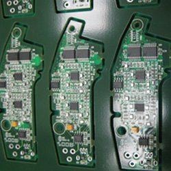
Board level integration starts at the connector footprint. A board mounted SMA or SMB connector sets the mating direction and the clearance available for the cable to turn. A heat sink, a standoff, or an enclosure wall can sit close to the connector. A straight mating body may then leave no room for the minimum bend radius. Checking that clearance during layout is far cheaper than discovering it at first article build.
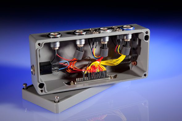
Box build integration adds the rest of the system. A complete build brings together printed circuit board assemblies, cable assemblies, wire harnesses, enclosures, and mechanical hardware. Testing then verifies the result as a unit. Coaxial routing has to coexist with everything else inside that volume. That usually means separating RF paths from power wiring and keeping runs away from switching components.
Coordinating PCB assembly, cable assembly, and final integration under one production plan can reduce handoff gaps.
Fit verification is the practical payoff. A first article build confirms connector orientation, cable length, bend radius, and tie down points in the real enclosure. Issues found there can be corrected on the drawing before volume production begins.
Electrical verification belongs in the same stage. Continuity testing checks electrical connections. RF and system testing assess signal performance and interference under defined operating conditions.
Documentation Requirements for Custom Coaxial Cable Assemblies
Documentation is what turns a set of engineering decisions into a part that can be built the same way every time. Documentation gaps can delay the transition from prototype builds to scheduled production.
A complete coaxial assembly package generally includes:
- A dimensioned drawing showing overall length, tolerance, connector orientation, and routing features
- Impedance, frequency range, and loss requirements
- Connector part numbers with gender, body style, and plating
- Cable construction details including shield type and jacket material
- Termination method, strip lengths, and torque values where applicable
- Strain relief and support requirements
- Labeling, marking, and serialization requirements
- Inspection and test criteria with pass and fail limits
- Approved sources and any substitution rules
- Revision level and change control process
Approved source control deserves attention. Stating which components may be substituted, and which may not, prevents well intentioned swaps that alter shielding or attenuation. Where a substitution is acceptable, defining the qualifying criteria keeps the decision consistent.
Acceptance criteria convert quality from opinion into measurement. Continuity checks, dimensional verification, and visual inspection standards give both sides a shared definition of a good part. Where electrical performance matters, the test method and the limits belong on the drawing.
Traceability requirements should be settled before the first production order. Lot level or unit level records support field investigations and change control, which regulated industries generally expect.
Moving custom coaxial cable assemblies from prototype to volume production goes more smoothly when the documentation package matures alongside the build, rather than being reconstructed after the design is frozen. Prototype builds are the right time to capture what the assembler actually did, then write it into the drawing.
Change control closes the loop. Once production starts, an undocumented change to cable, connector, or process can alter performance in ways that inspection will not catch. A defined revision process protects the work that went into the original specification.
Specifying coaxial cable assemblies well comes down to writing down decisions that often stay in someone’s head. Impedance and frequency set the electrical boundaries. Connector family, orientation, and termination method determine how the assembly behaves mechanically. Shielding and grounding decide how it performs near noise. Routing, strain relief, and environmental requirements determine how long it holds that performance. Documentation carries all of it into production without reinterpretation.
Defining assembly requirements early can reduce integration rework and support more consistent production. Star Engineering Inc. supports printed circuit board assembly, cable and wire harness assembly, electromechanical assembly, and box build integration. Learn how the team supports custom coaxial cable assemblies from prototype through production.
Frequently Asked Questions
The time depends on design complexity, available drawings, and testing requirements. Phase matching or environmental qualification can require additional engineering work.
Yes, but changes to cable, connector, or termination method can alter performance. Any change should go through revision control and verification before shipment.
Common causes include a bend below minimum radius, a loose threaded interface, or a shield terminated through a pigtail rather than to the connector body.
No. Semi rigid cable offers high shielding effectiveness but holds a formed shape, so it suits fixed routing rather than assemblies that move or flex.
Impedance, frequency range, length with tolerance, connector types and orientation, shielding construction, jacket material, environment, and test requirements. Meta Description and Social Snippet